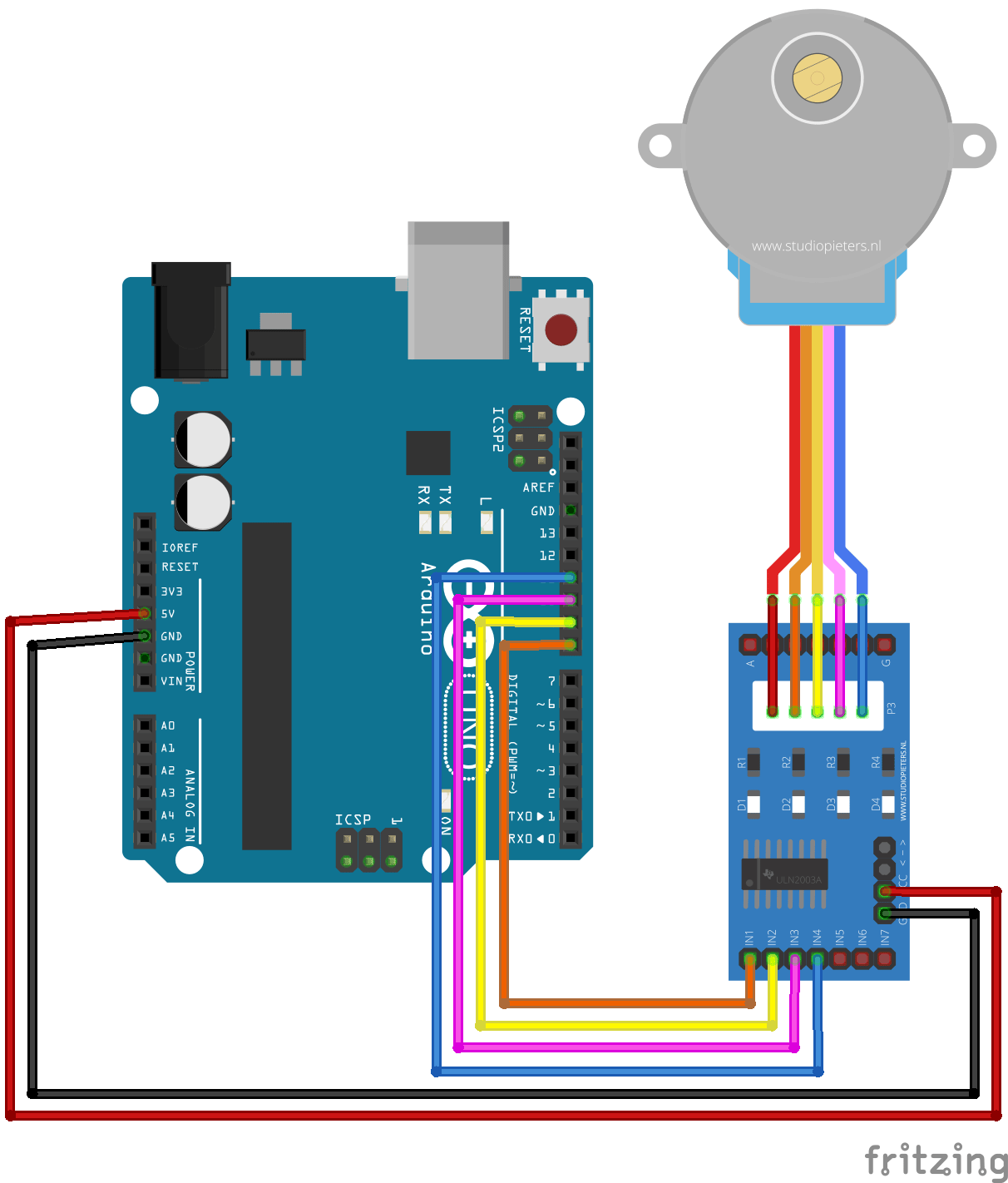
The switch pin (SW) is not used in this example. Using the X-axis and the Y-axis potentiometers we can control two stepper motors independently. Stepper motor control with Arduino and joystick code: In this example I used Arduino stepper motor library (built-in) which simplifies the code, it’s included in the code using the following line.
Introduction The gives you the capability to drive bipolar stepper motors between 150mA to 700mA per phase. Materials Required To follow along with this tutorial, we recommend you have access to the following materials. You can either solder directly to the Easy Driver, or use headers for attaching power supplies, motors, etc. The best option for you will be dependent on your application.
Suggested Reading If you aren’t familiar with the following concepts, we recommend reviewing them before beginning to work with the Easy Driver. Hardware Overview The Easy Driver is designed by, and is designed around the A3967 IC. This IC enables you to drive bipolar stepper motors that are 4, 6, or 8-wire configurations.
The board can either work with 3.3V or 5V systems, making it extremely versatile. Two mounting holes on-board give the user the option to mechanically stabilize the Easy Driver. Pin Descriptions Let’s take a look at all of the pins broken out from the A3967 IC on the Easy Driver.

See More On Tutorialspoint
Board Top Pins If you look across the top of the board, you will see several pins. They function as follows:. Coil A+ - H-Bridge 2 Output A. Half of connection point for bi-polar stepper motor coil A.
Coil A-H-Bridge 2 Output B. Half of connection point for bi-polar stepper motor coil A.
Coil B+ - H-Bridge 1 Output A. Half of connection point for bi-polar stepper motor coil B.
Coil B-H-Bridge 1 Output B. Half of connection point for bi-polar stepper motor coil B. PFD - Voltage input that selects output current decay mode.
If PFD 0.6Vcc, slow decay mode is activated. Hardware Hookup Connect Motor Coil Wires You will need to determine the wire pairs for each coil on the motor you plan to use.
The most reliable method to do this is to check the datasheet for the motor. Coil wire diagram from the our. However, if you are using a 4-wire or 6-wire stepper motor, it is still possible to determine the coil wire pairs without the datasheet.
For a 4-wire motor, take one wire and check its resistance against each of the three remaining wires. Whichever wire shows the lowest resistance against the first wire is the pair mate. The remaining two wires should show similar resistance between the two of them. For a 6-wire motor, you will need to determine which of three the wires go together for one coil.
Pick one wire, and test this against all other wires. Two wires should show some resistance between them and the first wire picked, while the other three will show no connection at all. Once the three wires for one coil have been determined, find two of the three that show the highest resistance between them. These will be your two coil wires. Repeat for the second group of three wires. Advanced email extractor pro registration cracked pepper.
Once you have determined the coil wire pairs, you will need to attach them to the Easy Driver. The first coil pair should be plugged into Coil A+ and Coil A-, while the second coil pair plugs into Coil B+ and Coil B. There is no polarity on the coils, so you don’t need to worry about plugging in a coil backwards on the board. In our example, we are using a 4-coil motor. The connections between the Easy Driver and motor are as follows. Easy Driver → Motor.

A+ → Green Wire. A- → Red Wire. B+ → Blue Wire. B- → Yellow Wire. Note: Do not connect or disconnect the motor while the Easy Driver is powered. Connect a Power Supply Once your motor is connected, you can then connect a power supply to the Easy Driver.
You can use any kind of power supply (desktop, wall adapter, battery power, etc.), but verify that whatever choice you go with is capable of providing up to 2A and falls in the range of 6V to 30V. Connect the power supply to M+ and GND. REMEMBER to disconnect the power before connecting/disconnecting your motor.
Connect a Microcontroller For this example, we will be using the. However, any microcontroller that works at 3.3V or 5V logic and has digital I/O with PWM capability will work for this example. Here are the following pin connections for our example. RedBoard → Easy Driver. D2 → STEP. D3 → DIR.
D4 → MS1. D5 → MS2. D6 → ENABLE Final Circuit Once you have everything connected, your circuit should look like the following.
In 2003, CU student Nate Seidle blew a power supply in his dorm room and, in lieu of a way to order easy replacements, decided to start his own company. Since then, SparkFun has been committed to sustainably helping our world achieve electronics literacy from our headquarters in Boulder, Colorado. No matter your vision, SparkFun's products and resources are designed to make the world of electronics more accessible. In addition to over 2,000 open source components and widgets, SparkFun offers curriculum, training and online tutorials designed to help demystify the wonderful world of embedded electronics.

We're here to help you start something.